This design replaces the previous version. There are also additional files applying to the underframe and brake details etc. The previous design will be removed from the files.
The files also include a drawing of the vehicle and a parts list for the model. Note the additional, non-3d printed requirements.
Horse boxes were fully fitted for passenger trains and classified as non-passenger coaching stock (NPCS) allowing them to travel at express speeds. They could be found anywhere in the UK, but especially in the northern areas. The LYR D108 was designed by Frederick Attock.
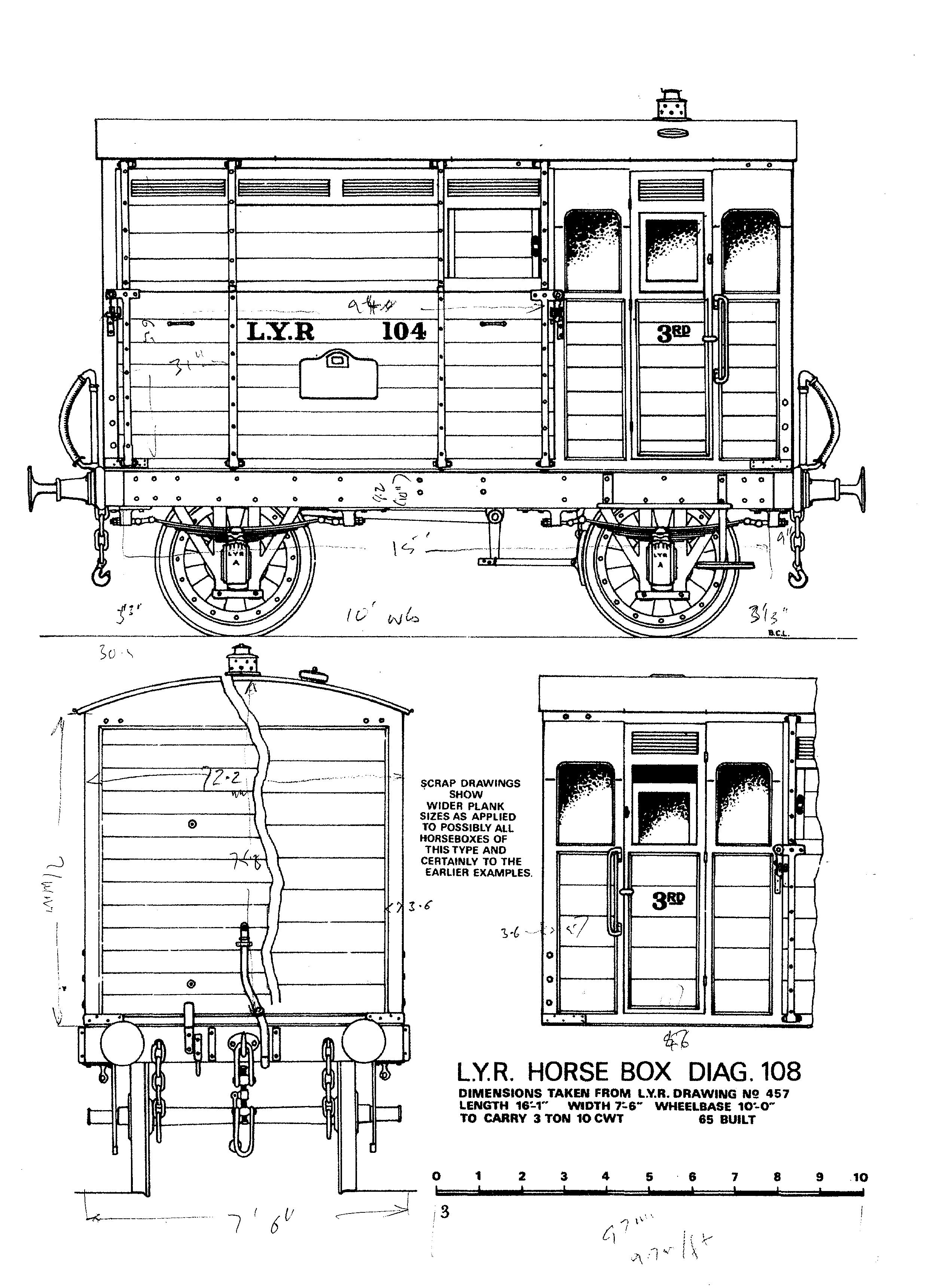
Drawing of vehicle
Documents
Document
A list of parts required to complete the model.
Models
3D Model
Separate files for sides, ends, partition and floor will be listed later.
3D Model
It is suggested that the roof is printed mounted vertically so the layer lines run circumferentially. It is also suggested that the roof is retained by the use of small magnets.
3D Model
Print the subframe flat on the print bed, with the rounded beading above the buffer beams uppermost. Note the holes in the cross-beams for mounting the bolsters later.
3D Model
Check the depth of the countersink after printing, to ensure that your chosen screws (M2 or 6BA) will sit flush when tightened..
3D Model
Print two off. After printing check the patency of the three holes across the width against your steel rods, which should be able to be inserted without too much force. Gently, thread the screw holes at the ends (6BA/M2) for your chosen screws. You need to be able to remove at least one W-iron from the bolster to insert/remove the wheel/axle assembly, but one W-iron can be glued in place if required.
3D Model
You will need a length of 3mm/1/8" silver steel rod for the axle. To retain the back to back dimension it is recommended that a 40mm length of brass tube is slid on the axle, between the wheels before they are pushed on to the axle. Wheels can be painted before fitting to the axles.
3D Model
Glue the brake gear into the corner between the solebar and the medial cross-beams. Note the brake shoes should be inbound. These early vehicles only had one pair of brake shoes working on a single axle. You will also require a suitable length of 1mm silver steel rod to fit beneath the solebars and allow for mounting of the brake lever.
3D Model
The W-irons and bolsters should be free to move from the springs. One bolster assembly is fixed in position with two rods in the outer lateral holes in bolster and crossbeams. The other bolster is allowed to pivot on a single rod inserted through the central holes.
3D Model
The brake lever was only mounted on one side of the vehicle (on the port side, assuming the groom compartment is forwards).
3D Model
These are mounted at each end of the brake activation rod. When mounted on the rod, glue them to the solebar, with a small amount of rod emerging for the brake lever. Fit the brake cylinder lever before gluing the rod in place.
3D Model
The rack is glued to the solebar at the rear end of the port side.
3D Model
The brake cylinder will be glued to the floor of the vehicle and the operating arm fixed in an adjacent position.
3D Model
It is recommended that these are printed in TPU for flexibility and resilence.
3D Model
These should be a push fit into the holes on the buffer beams. A dab of glue will suffice if needed to secure. You will need steel buffer heads available (with springs and nuts) from Peter Korzelius or Tenmille. The buffer heads can be inserted in the shanks before they are fitted into the. buffer beams. Check the freedom of movement after insertion.
3D Model
Recommended printed using TPU for flexibility.
Reviews/Comments (subject to moderation)